Sidebar
LPWAN IoT Use Case: LoRa to AWS
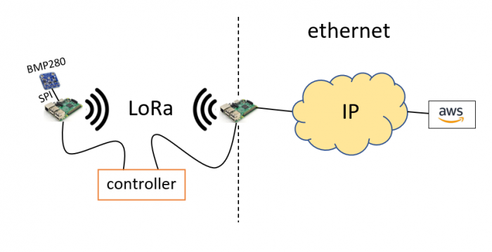
Now, let's try to set up a real life LPWAN IoT topology. Consider the following scenario:
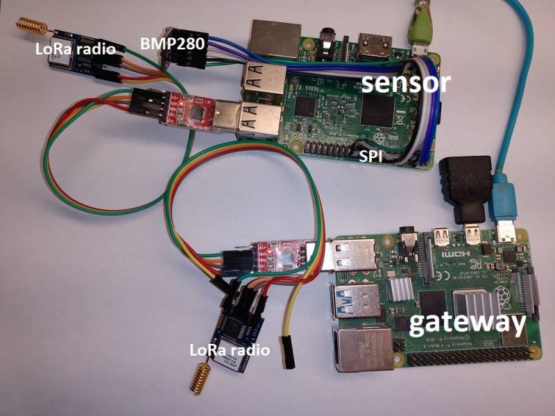
One embedded device (i.e. raspberry pi) running a Netualizer agent receives temperature and pressure readouts from a BMP280 temperature sensor. The BMP280 and the raspberry pi are connected by means of a SPI I/O interface. Readouts are encapsulated on top of CoAP and transmitted over LoRa a few kilometers away to another rapsberry pi. This second raspberry pi, that acts as a gateway, decapsulates the BMP280 readouts and encapsulates them into MQTT for transmission over Ethernet to AWS. A single controller configures and deploys both devices in the field. The real devices look like this:
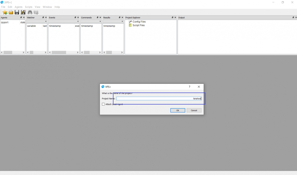
Let's create a new project by clicking on File ⇒ New ⇒ Project and name it loraAws. Make sure that the local built-in agent does not get attached (uncheck box):
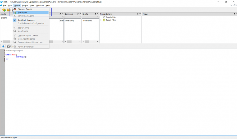
Now, let's attach the agent running on the device sensor by clicking on Agents ⇒ Add Agent:
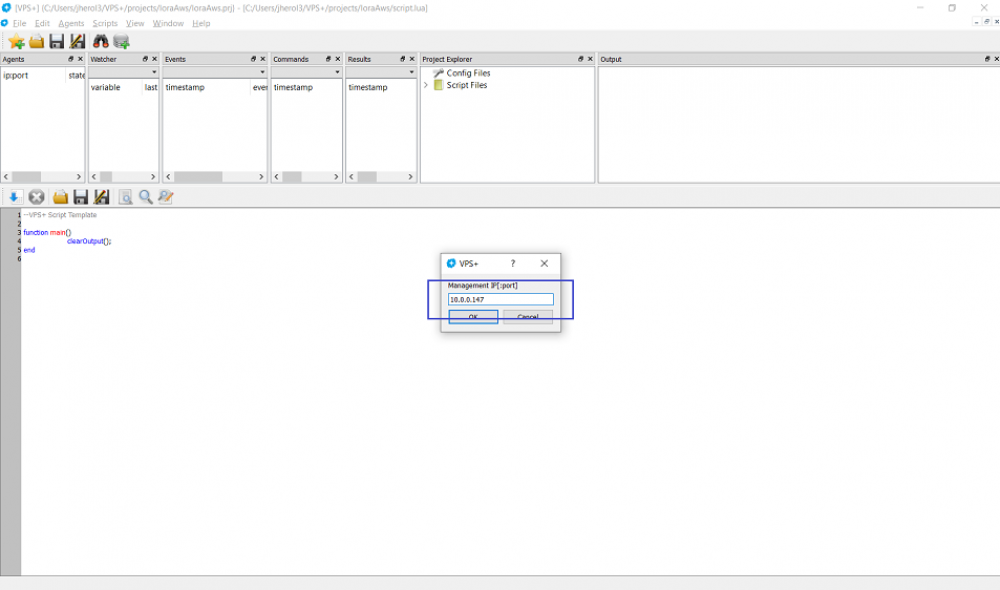
Then enter the management IP address of the raspberry pi that runs the Netualizer agent:
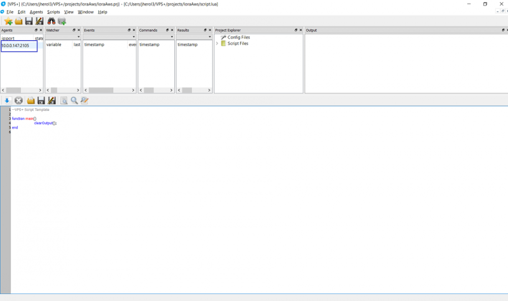
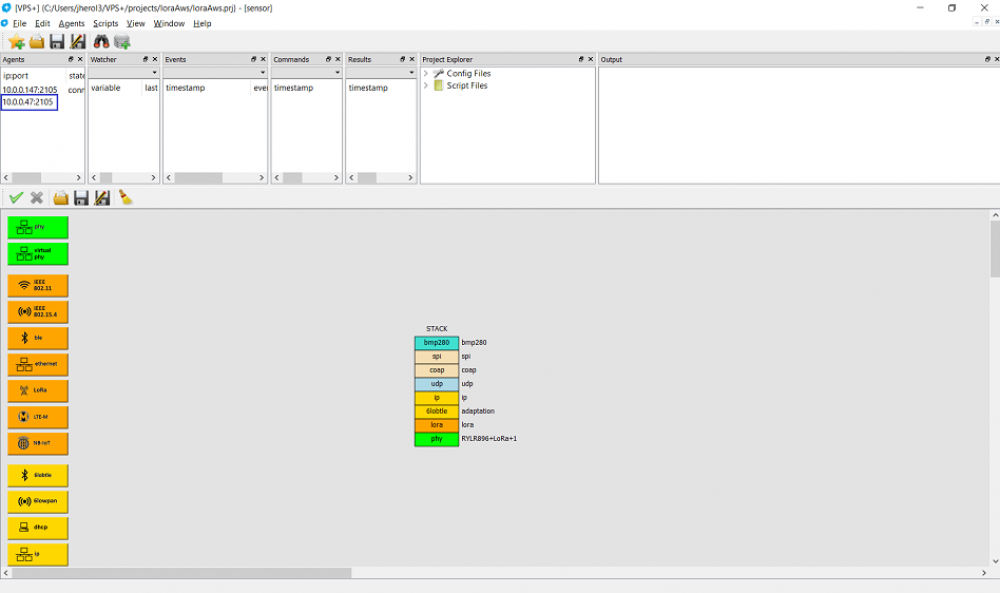
Double click on the agent entry:
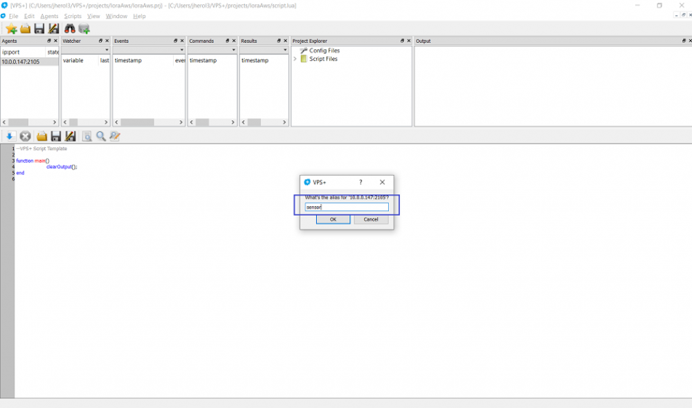
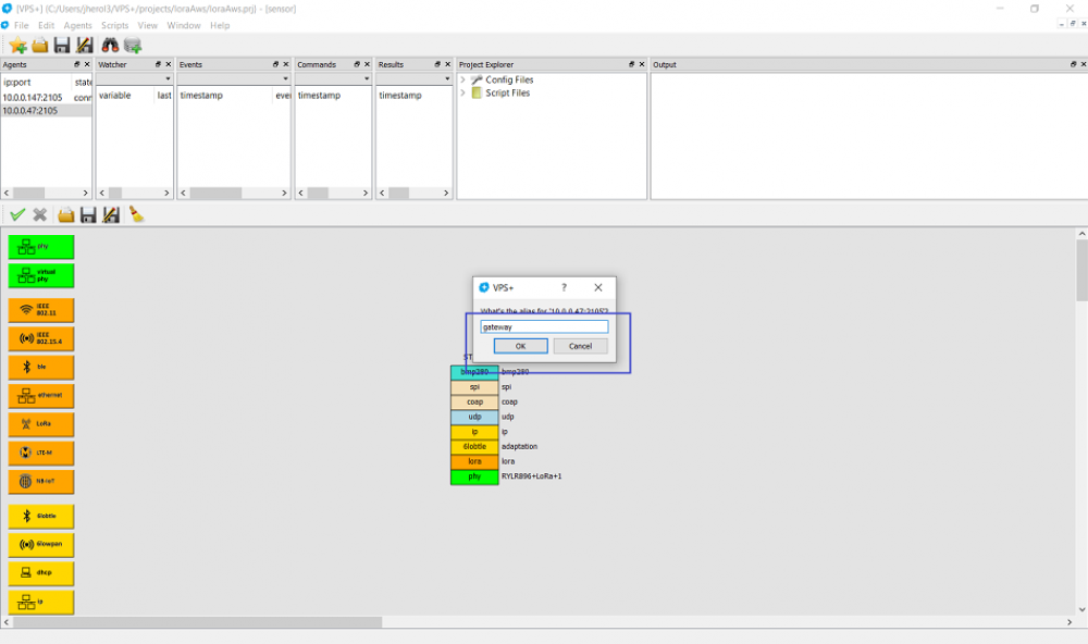
And let's name it sensor:
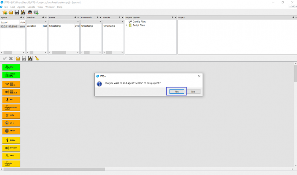
Now, attach this Netualizer agent to the project by entering Yes:
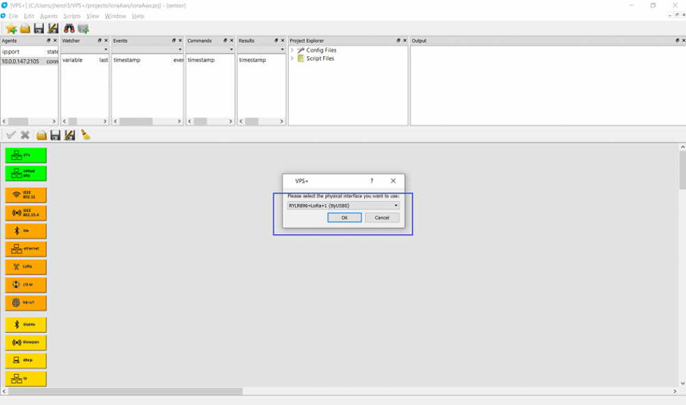
Then add the physical layer and select the LoRa radio:
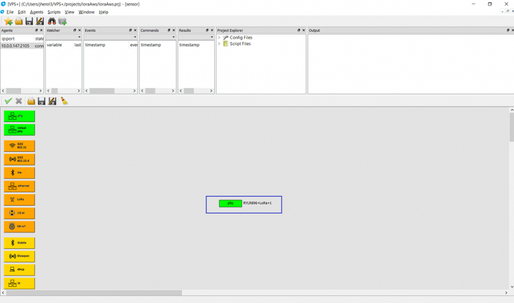
And place the physical layer on the configuration:
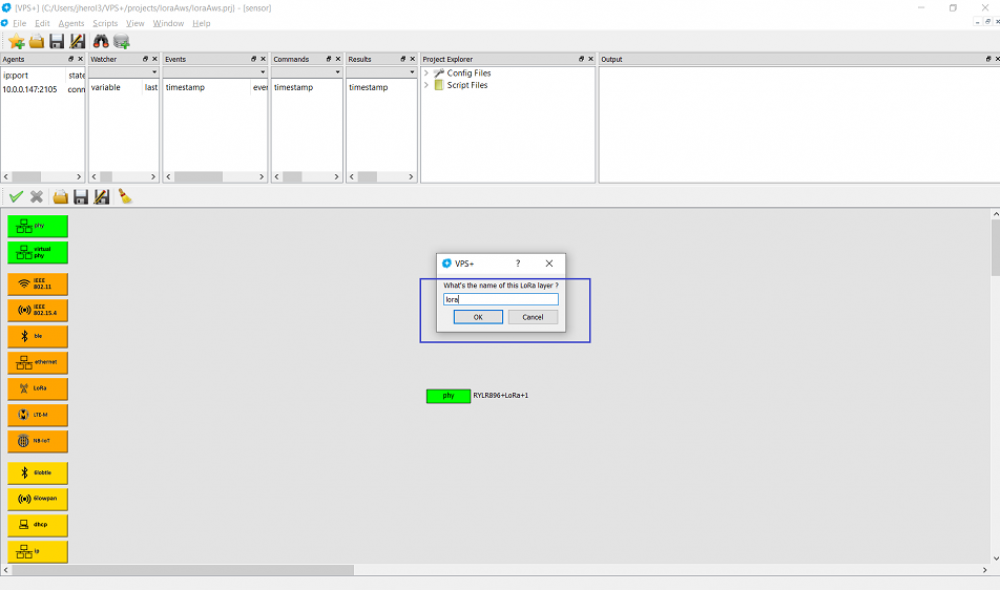
Let's add a LoRa layer and name it lora:
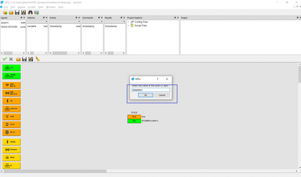
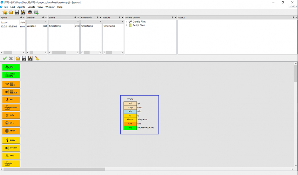
And place it on top of the physical layer. In order to support IPv6 over LoRa, we need an adaptation layer as LoRa cannot handle the minimum 1280-byte MTU size of IPv6 datagrams. We can use the Bluetooth Low Energy (BLE) IPv6 adaptation mechanism for this. Therefore, create a new 6LoBTLE layer and name it adaptation:
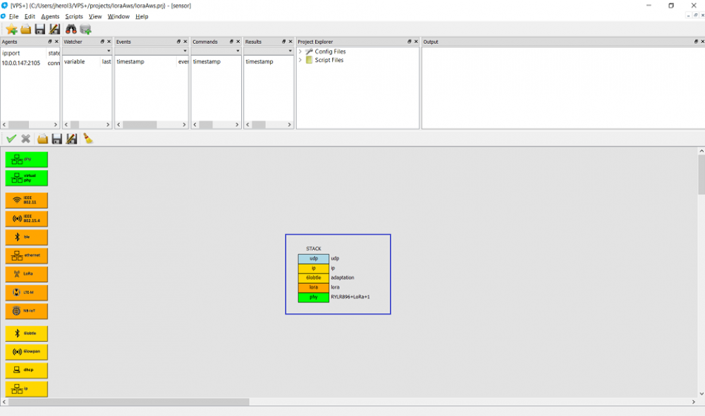
Similarly, place the adaptation layer on top of the lora layer. Next, add IP and UDP layers and respectively name them ip and udp. Keep the defaults:
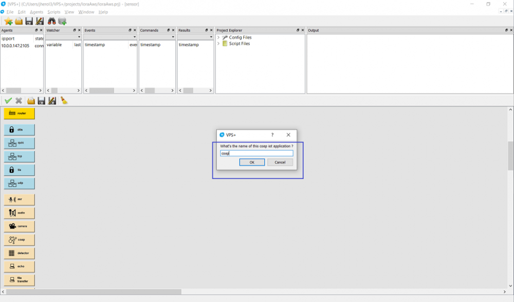
Then create a CoAP layer, name it coap:
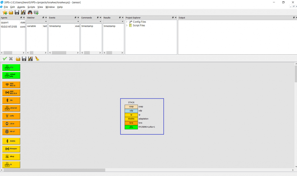
And place it on top of the udp layer:
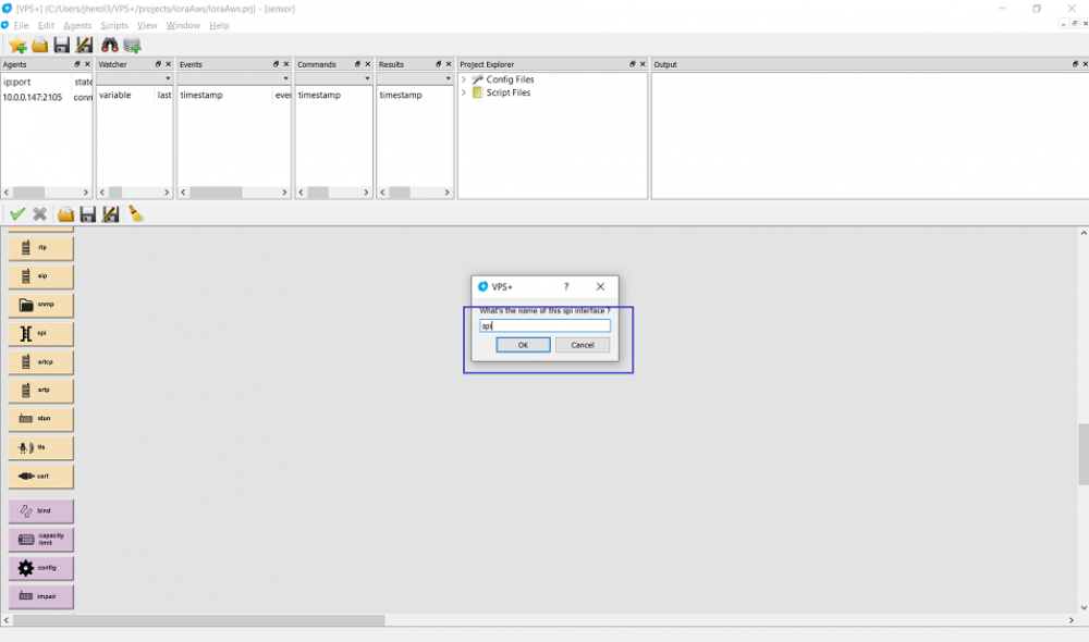
Let's add the SPI interface and call it spi:
Put it on top of the coap layer:
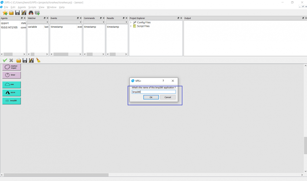
To avoid configuring every single layer to support the sensor, let's create a BMP280 helper layer instead and call it bmp280:
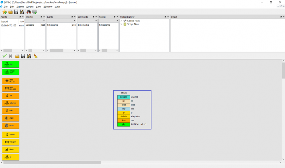
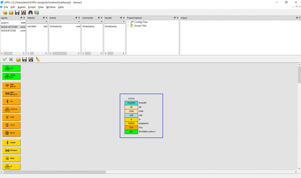
Then place it on top of the bmp280 layer. This finalizes the stack on the sensor device:
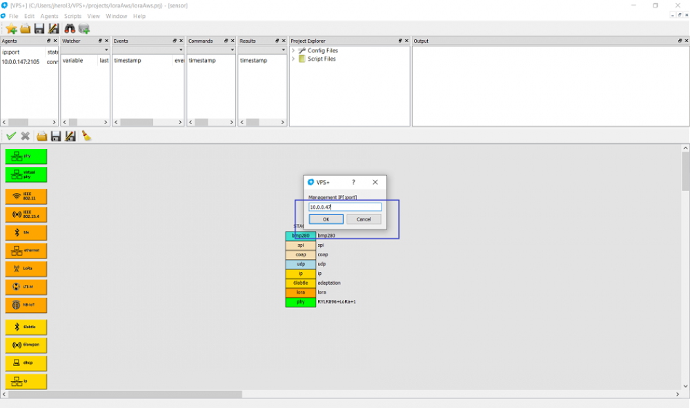
We will get back to this stack later to configure a few more things. For now, let's configure the gateway, add a new agent by clicking on Agents ⇒ Add Agent and enter the management IP address of the Netualizer agent running on the gateway device:
Then double click on the agent entry:
And name the configuration gateway:
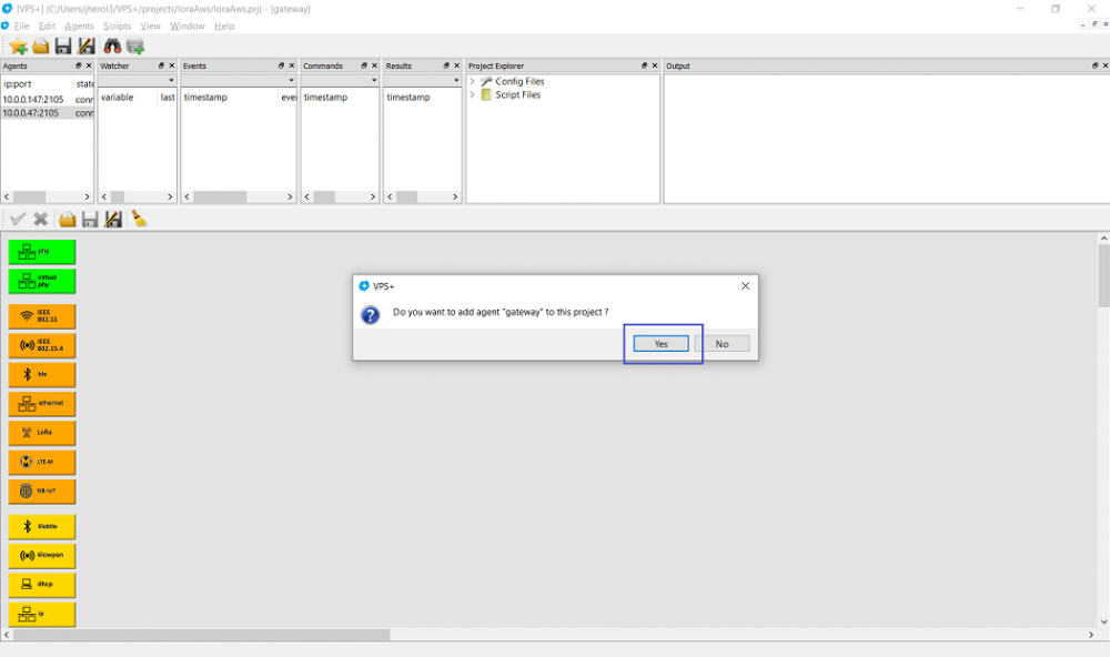
Add it to the project:
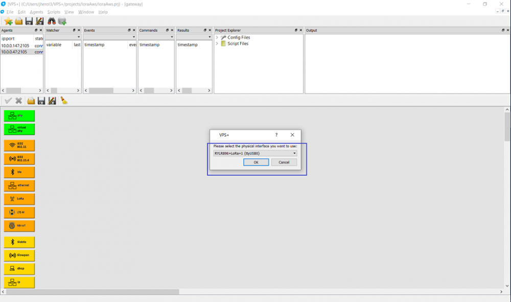
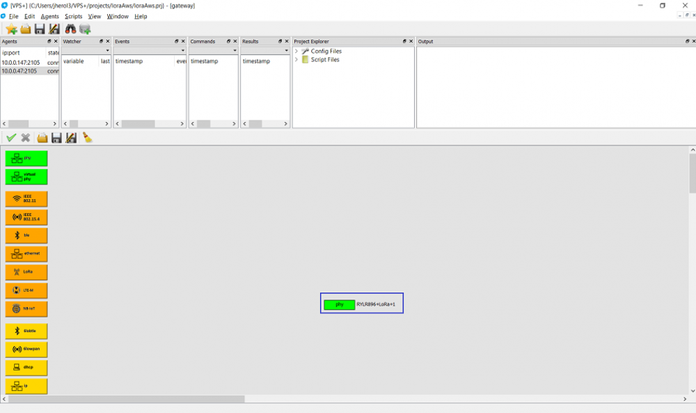
Let's build the LoRa stack first. Create a physical interface and select the LoRa radio:
Place it on the configuration:
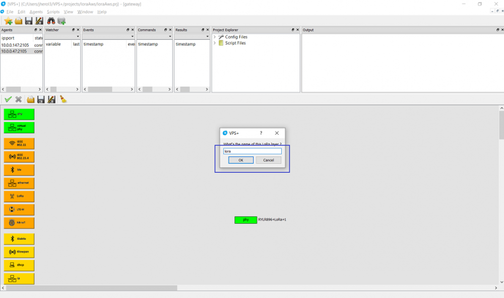
Add a LoRa layer and name it lora:
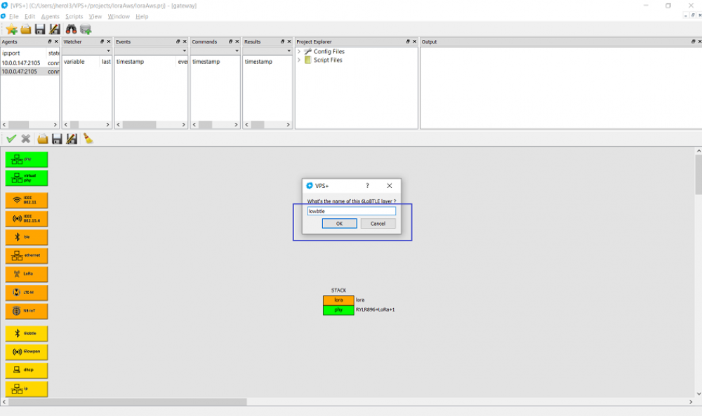
And place it on top of the physical layer. As before, create a new 6LoBTLE adaptation layer and name it lowbtle:
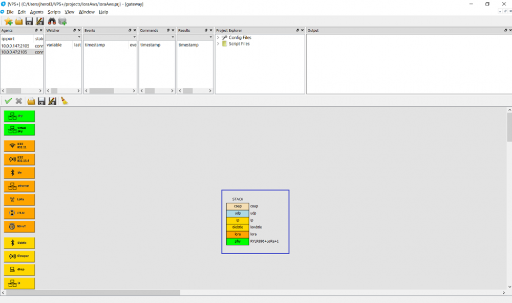
Let's build the whole stack up to the CoAP layer as we did for the sensor device, keeping all default parameters:
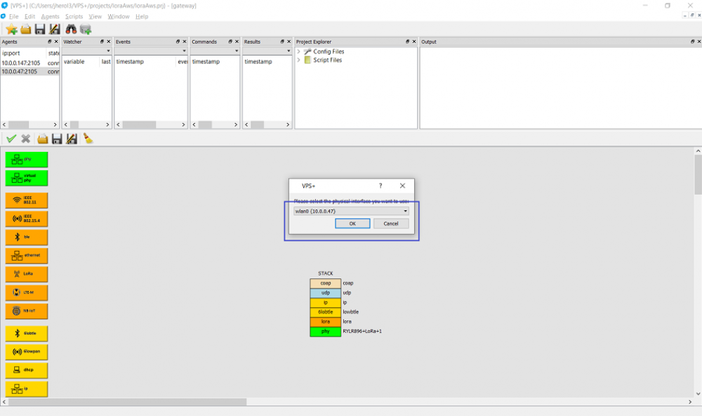
Now we need a stack for the other side of gateway. This is the stack that connects to AWS. First create another physical layer and select the wlan0 interface to connect the public Internet:
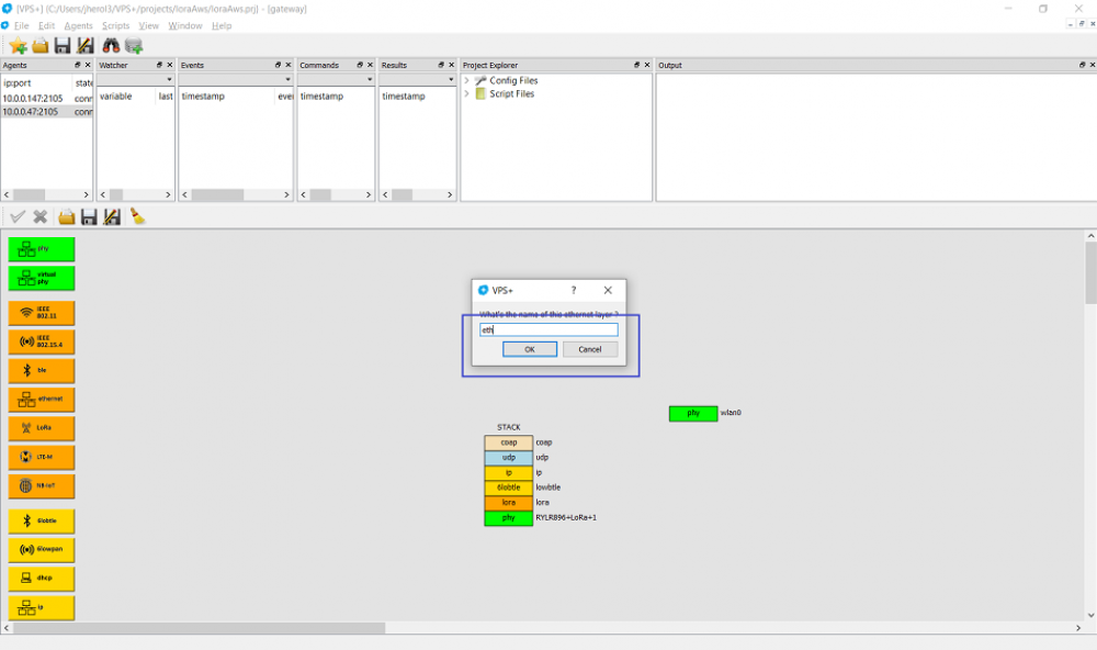
Then add an ethernet layer that name it eth:
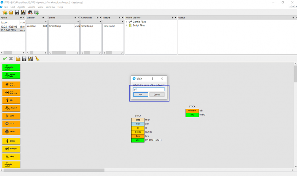
Place this layer on top of the physical layer and create an IP layer that we name ip2 since ip is already in use:
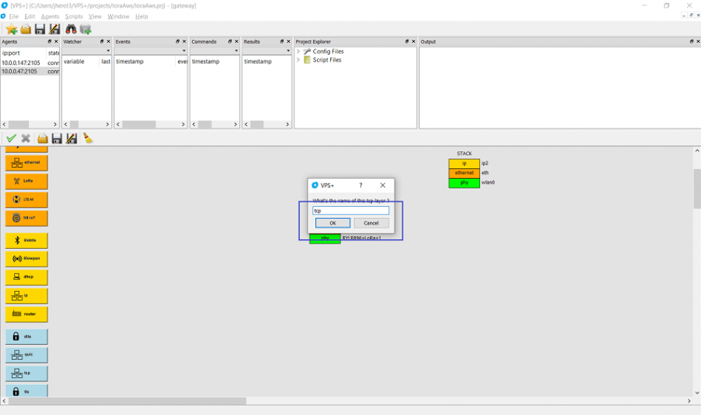
The ip2 layer is placed on top of the physical layer and a TCP layer is created and named tcp:
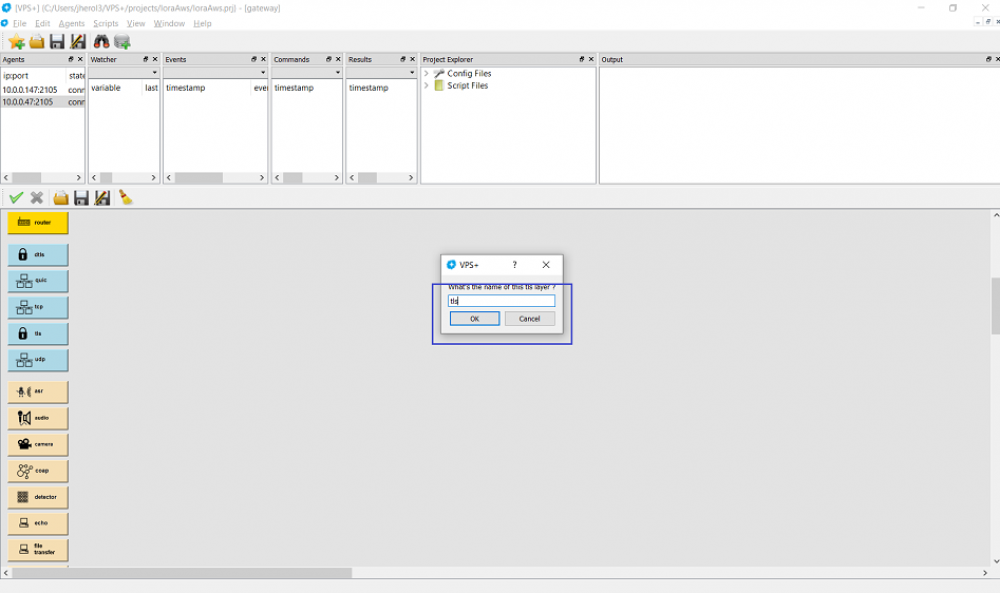
tcp is put on top of the IP layer. To interact with AWS, we need security so we add a TLS layer that is named tls:
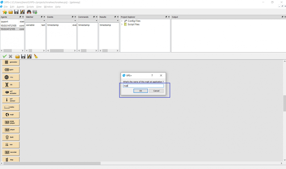
The TLS layer is placed on top of the TCP layer. Now let's create an MQTT layer to talk to AWS IoT, it can be named mqtt:
This layer is placed on top of the TLS layer:
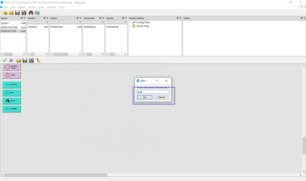
Next thing we need is access to AWS. Rather than configuring every stack to support it we can create an AWS layer and name it aws:
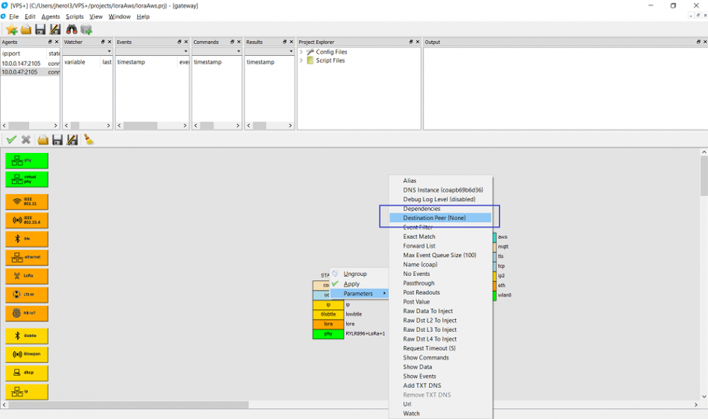
Place the aws layer on top of the mqtt layer. This finalizes the stack. Now, we can configure a few more things. Let's forward every packet that arrives a the coap layer must be forwarded to the aws layer. We can right click on the coap layer and click on Destination Peer
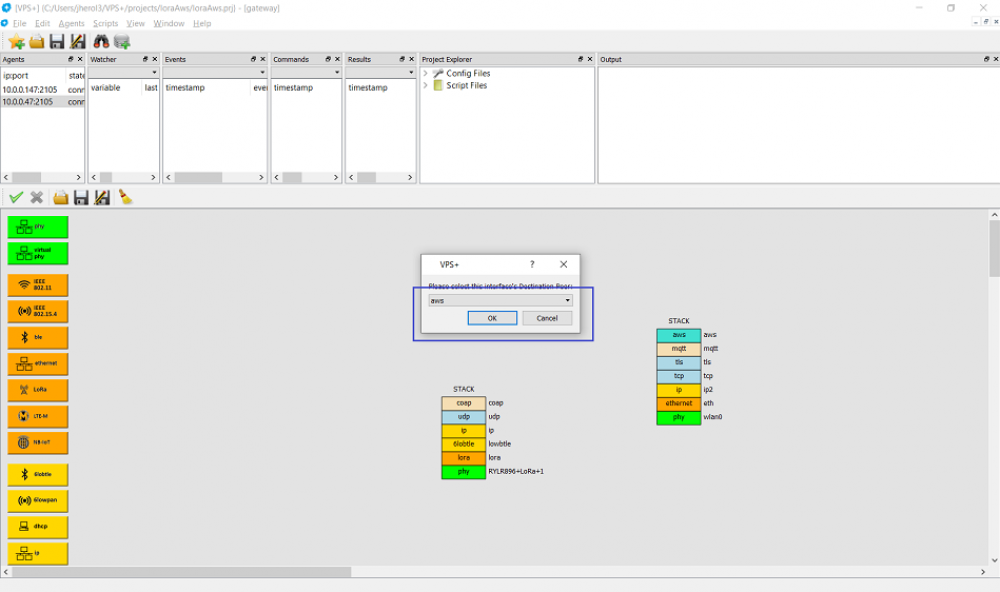
Let's select the aws layer as destination:
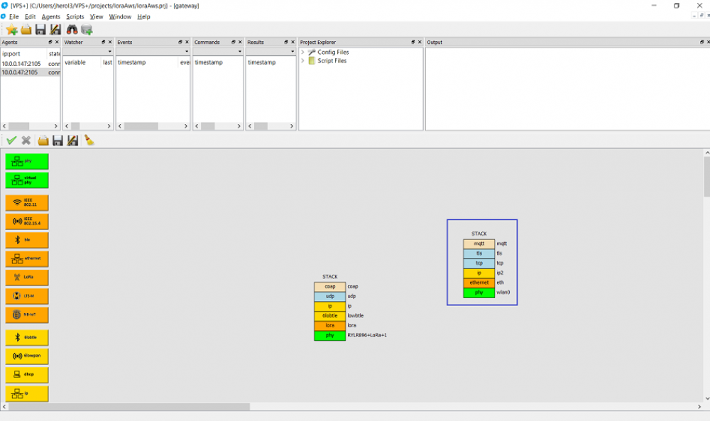
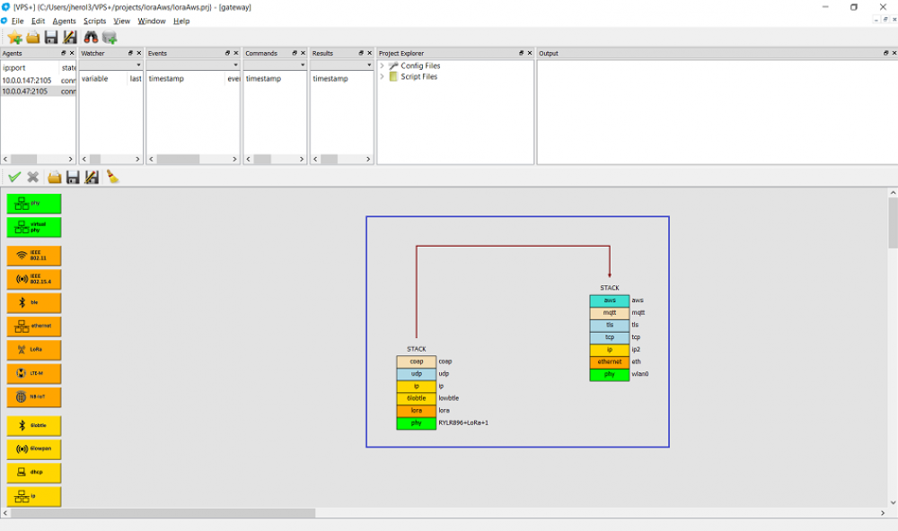
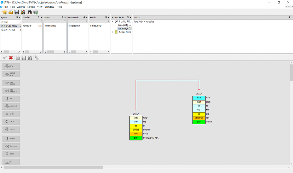
After this the configuration shows the packet path between one stack and the other:
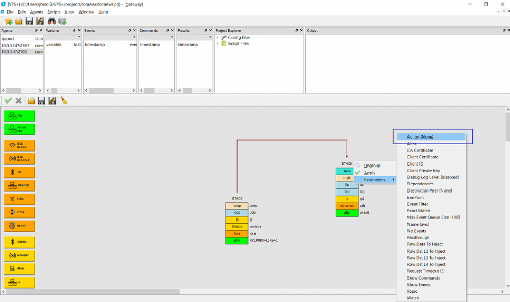
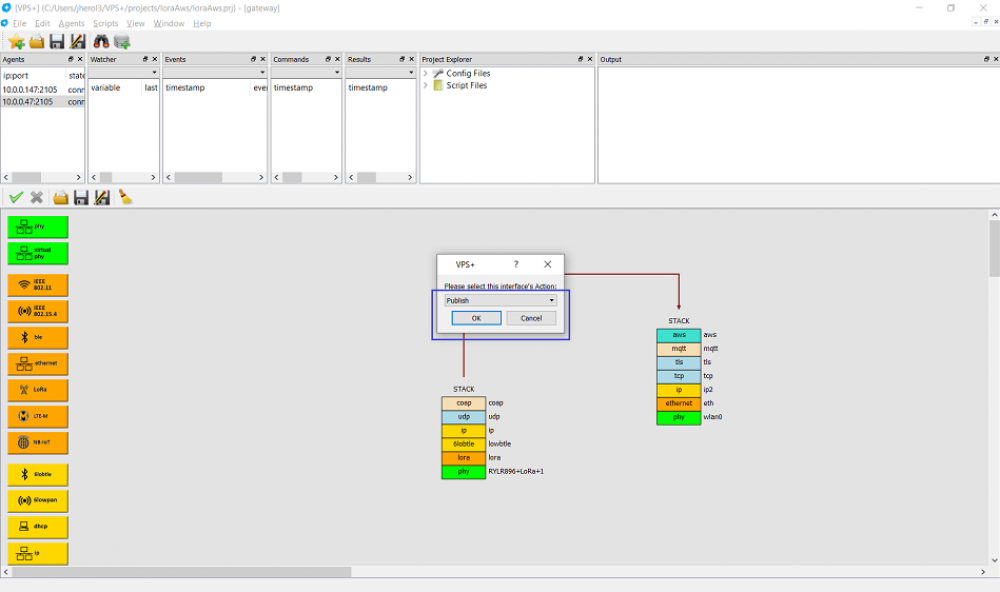
Now, let's configure the aws layer. Let's right click on the layer and select Action:
Then click on publish to push the readouts that arrive to the AWS layer into AWS IoT:
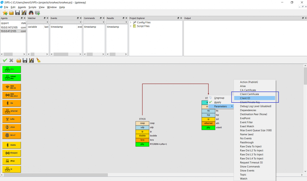
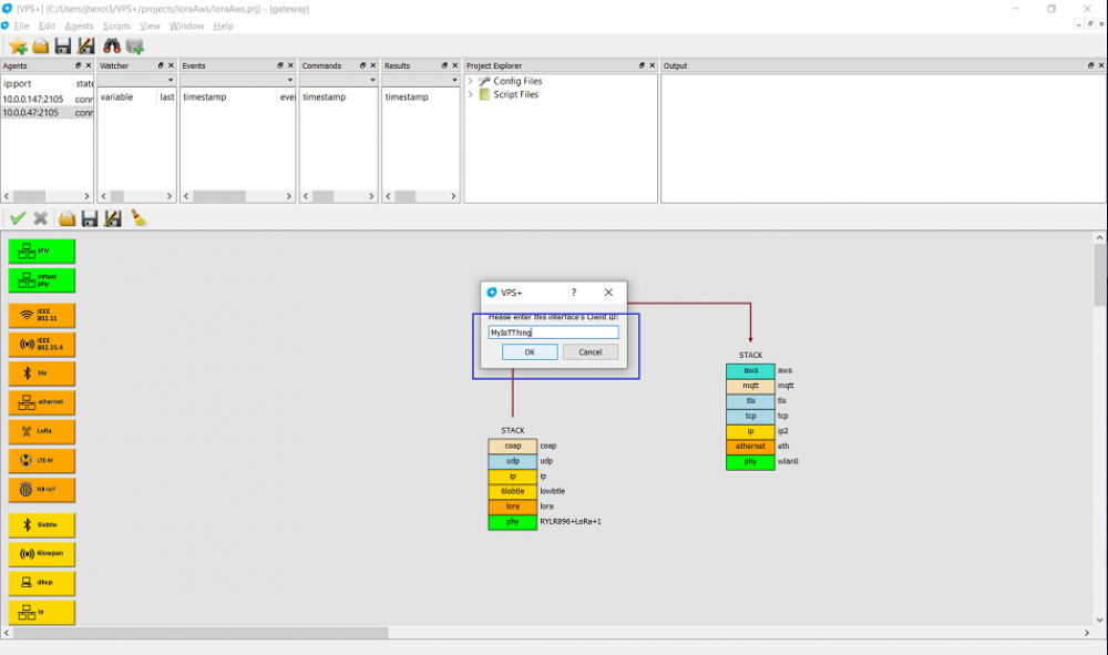
Then change the Client ID to match the AWS console information:
Copy/paste the information:
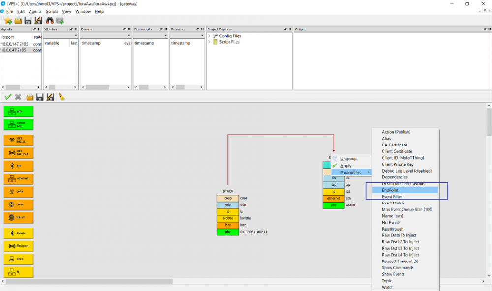
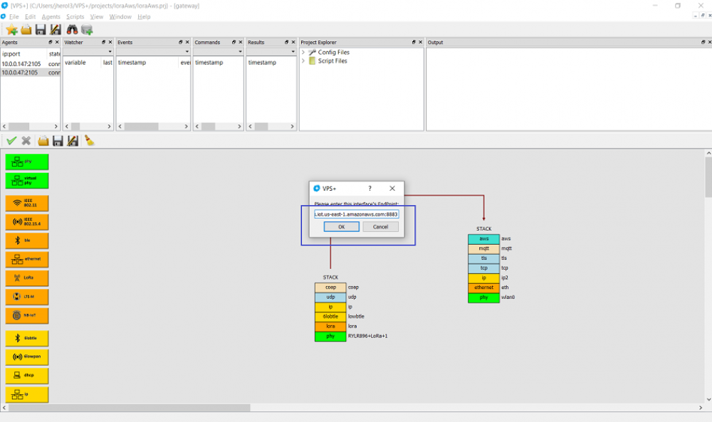
Similarly, select the EndPoint to match the AWS console information:
Copy/paste the information:
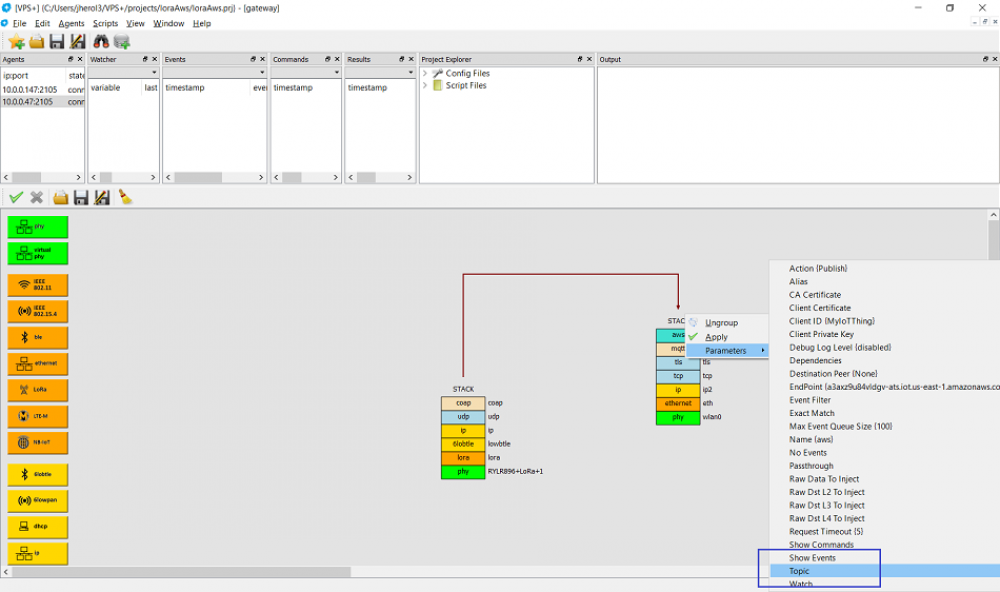
Then select the Topic field:
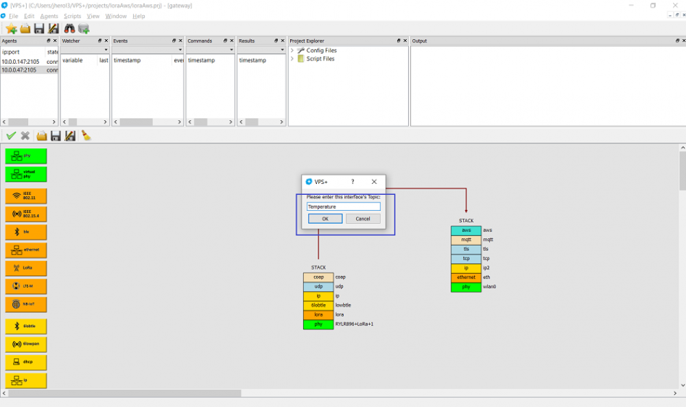
And enter Temperature:
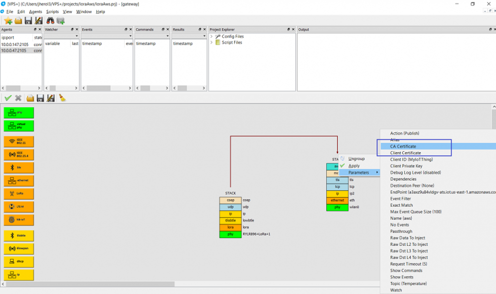
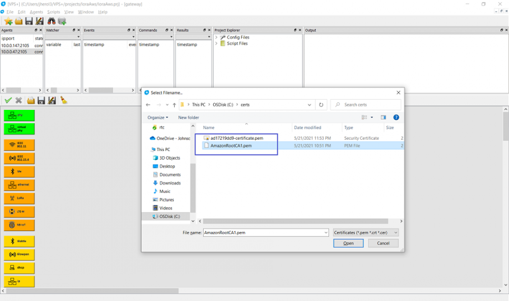
Click on the CA certificate:
And select the file:
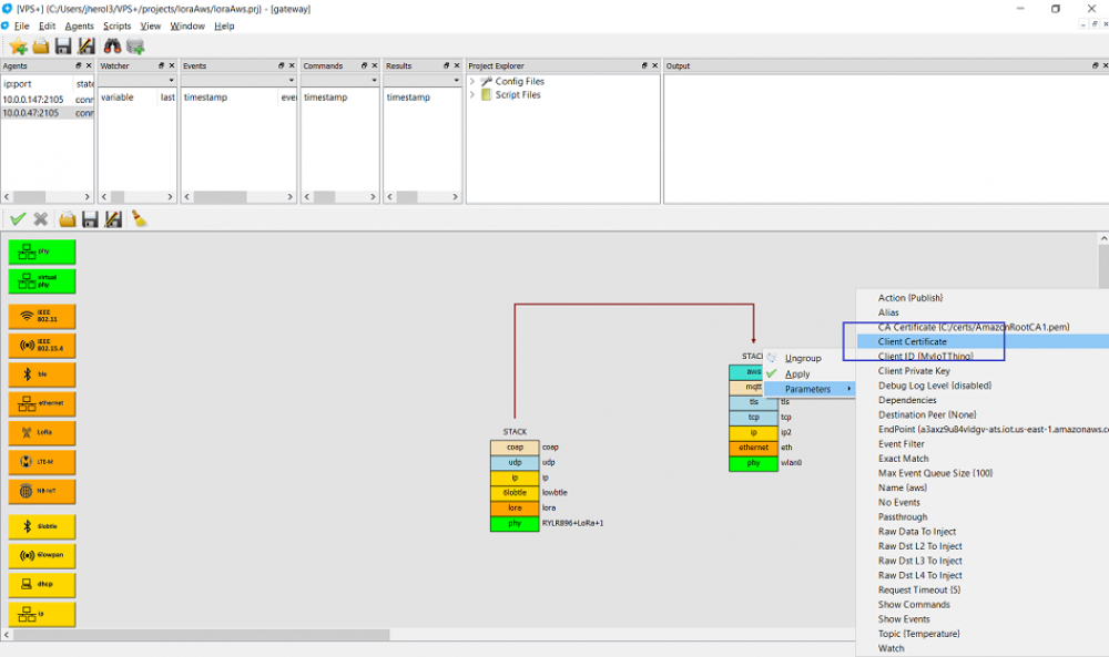
Also click on the Client certificate:
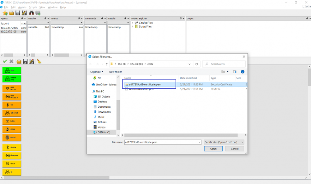
And select the corresponding file:
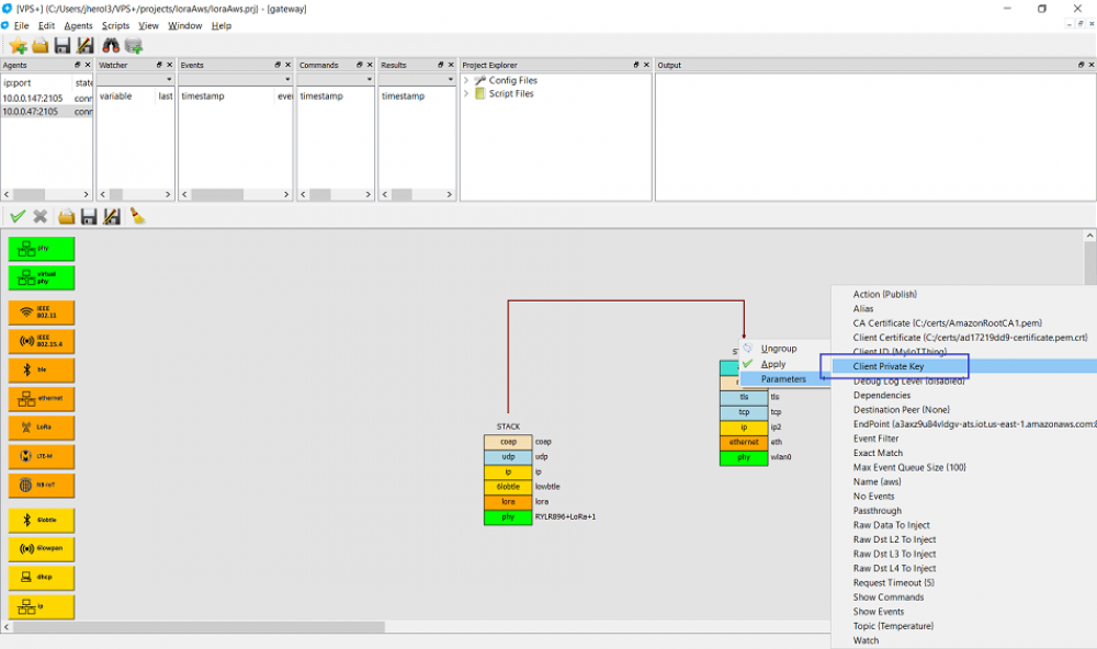
Finally select Client private key (and select the corresponding file):
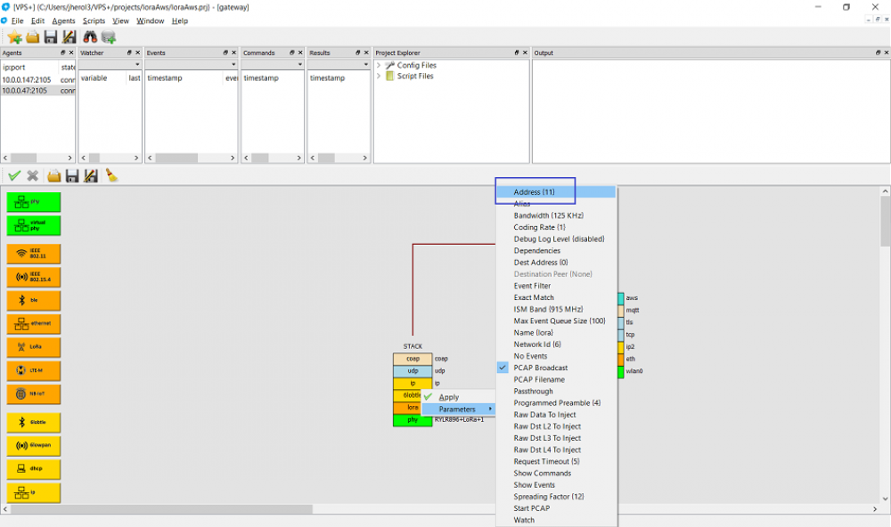
Now, let's figure out what the LoRa address is by right clicking on that layer. It should say (if defaults are used) 11:
As promised, let's go back to the device sensor by double clicking on the agent entry:
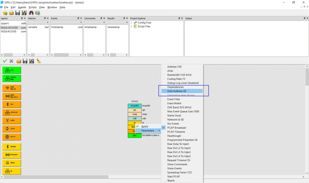
Right click on the LoRa layer and select Dest Address to change the destination address:
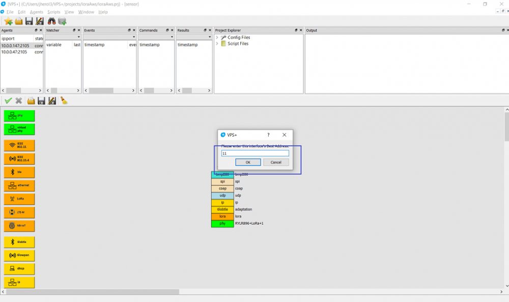
Enter 11 as destination address:
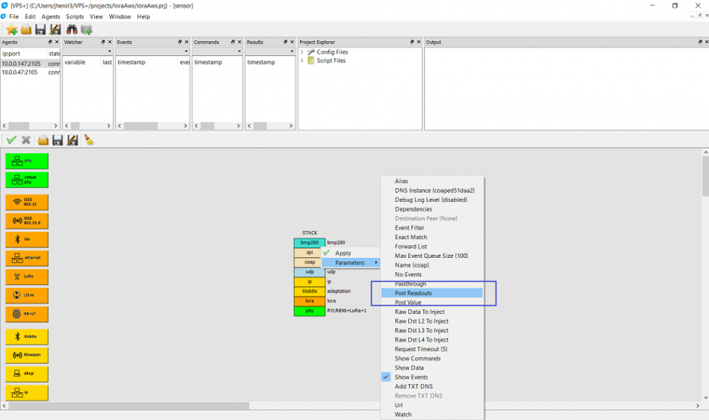
On the CoAP layer, enable Post Readouts to push readouts to the gateway device:
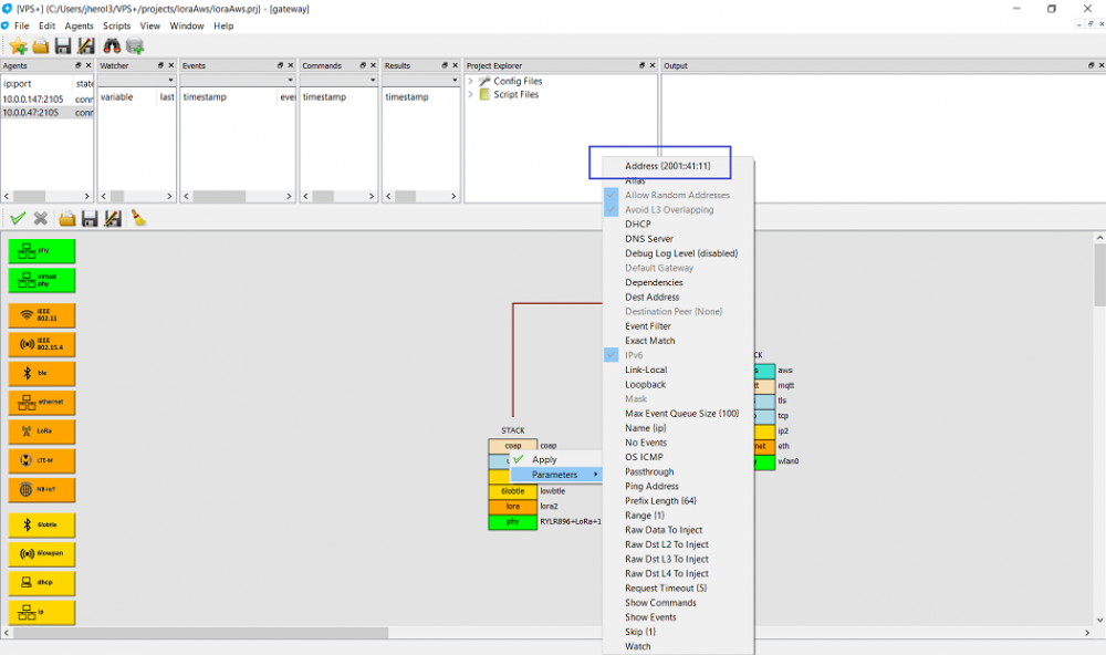
On the gateway device, right click on the IP layer of the LoRa stack to figure out what the destination IPv6 address is:
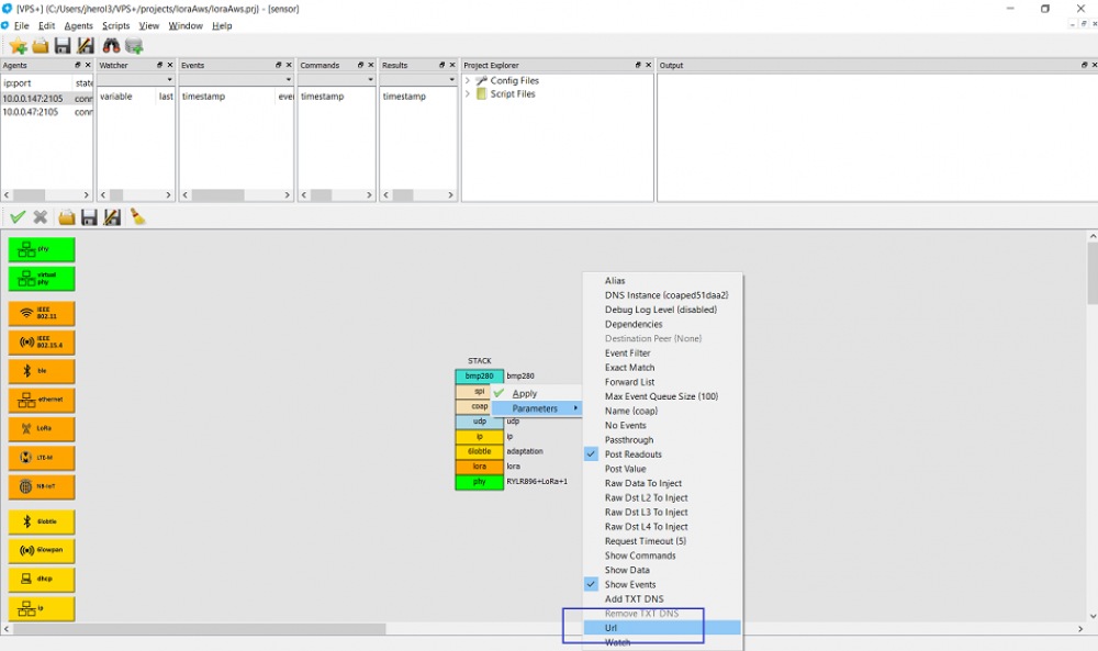
Back on the sensor device, change the Url field to specify the CoAP server on the gateway device:
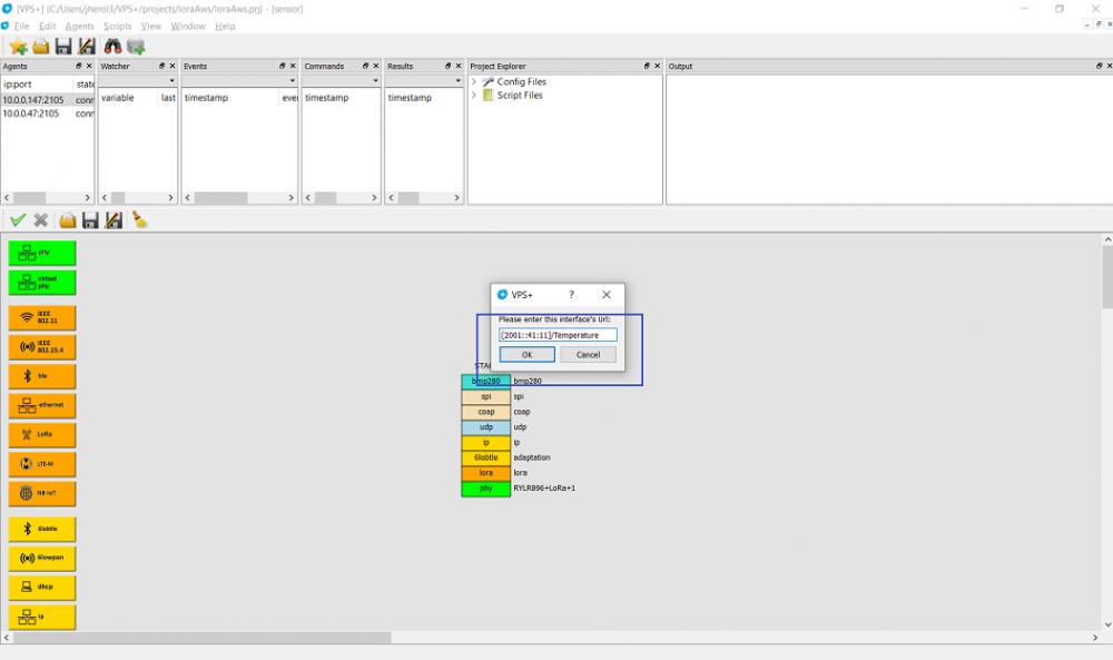
Enter the URL as [IP Address]/Temperature:
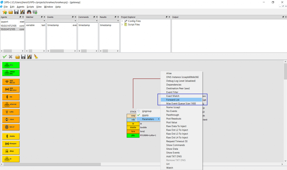
Then on the gateway device select the CoAP layer select the Forward List:
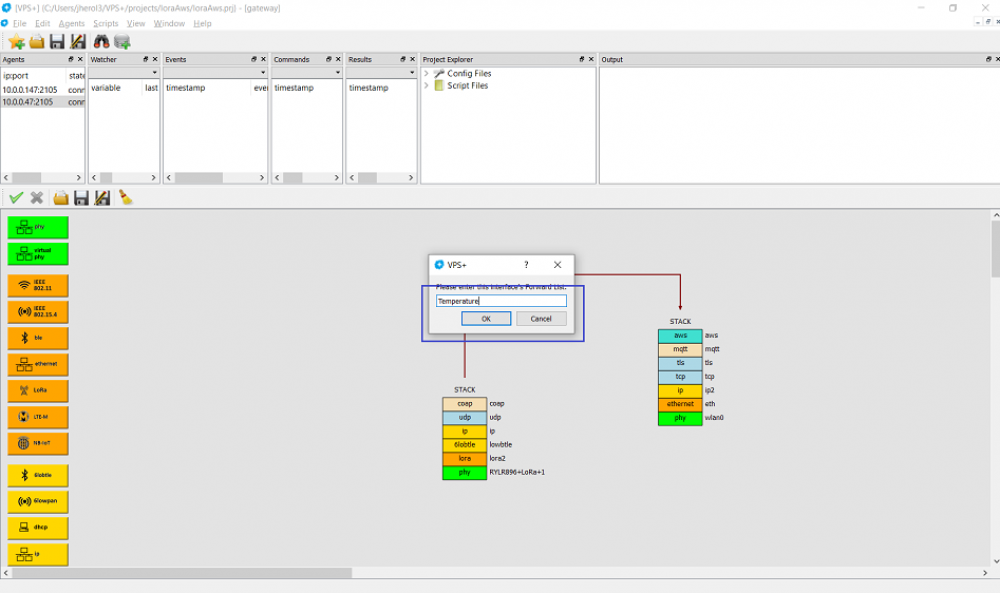
And enter Temperature:
Then we can start the suite by clicking on Scripts ⇒ Run Suite
We can look at the device on the AWS Console:
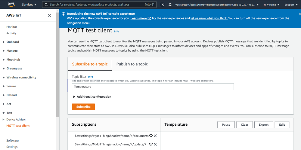
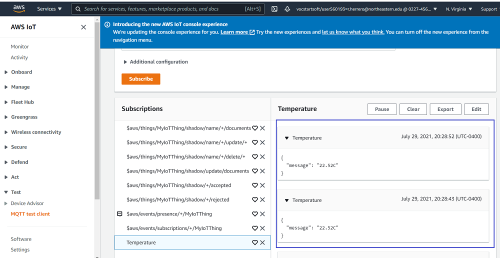
And launch a client to subscribe to Temperature readouts:
After a few seconds we can see the temperature readouts showing up:
That's it. We have a temperature sensor pushing readouts using CoAP over LoRa and arriving to a gateway that pushes them to AWS.

